General Frequency Considerations
The frequency response of an amplifier refers to the frequency range in which the amplifier will operate with negligible effects from capacitors and device internal capacitance. This range of frequencies can be called the mid-range.
• At frequencies above and below the midrange, capacitance and any inductance will affect the gain of the amplifier.
• At low frequencies the coupling and bypass capacitors lower the gain.
• At high frequencies stray capacitances associated with the active device lower the gain.
• Also, cascading amplifiers limits the gain at high and low frequencies.
Bode Plot
A Bode plot is a graph of the logarithm of the transfer function of a linear, time-invariant system versus frequency, plotted with a log-frequency axis, to show the system's frequency response. It is usually a combination of a Bode magnitude plot (usually expressed as dB of gain) and a Bode phase plot (the phase is the imaginary part of the complex logarithm of the complex transfer function).
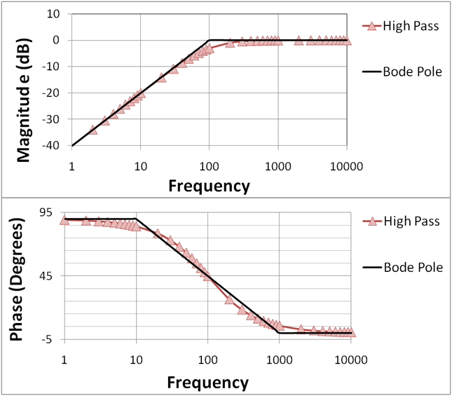
Figure 1(a): The Bode plot for a first-order (one-pole) highpass filter; the straight-line approximations are labeled "Bode pole"; phase varies from 90° at low frequencies (due to the contribution of the numerator, which is 90° at all frequencies) to 0° at high frequencies (where the phase contribution of the denominator is −90° and cancels the contribution of the numerator).

Figure 1(b): The Bode plot for a first-order (one-pole) lowpass filter; the straight-line approximations are labeled "Bode pole"; phase is 90° lower than for Figure 1(a) because the phase contribution of the numerator is 0° at all frequencies.
Cutoff frequency
In physics and electrical engineering, a cutoff frequency, corner frequency, or break frequency is the minimum frequency or energy of an incident wavelength required by an electron to overcome its binding energy.
Typically in electronic systems such as filters and communication channels, cutoff frequency applies to an edge in a lowpass, highpass, bandpass, or band-stop characteristic – a frequency characterizing a boundary between a passband and a stopband. It is sometimes taken to be the point in the filter response where a transition band and passband meet, for example as defined by a 3 dB corner, a frequency for which the output of the circuit is -3 dB of the nominal passband value. Alternatively, a stopband corner frequency may be specified as a point where a transition band and a stopband meet: a frequency for which the attenuation is larger than the required stopband attenuation, which for example may be 30 dB or 100 dB.
In the case of a waveguide or an antenna, the cutoff frequencies correspond to the lower and upper cutoff wavelengths.
Cutoff frequency can also refer to the plasma frequency.
Electronics
In electronics, cutoff frequency or corner frequency is the frequency either above or below which the power output of a circuit, such as a line, amplifier, or electronic filter is the power of the passband.[1] In electronics, decibel numbers refer to power. When directly comparing two powers P1 and P2, this is simply 10 * log(P1 / P2). However, one frequently compares two different voltages V1 and V2. In this case, the decibel is defined as 20 * log(V1 / V2). (In many circuits, power is proportional to the square of the voltage; this square results in multiplying the logarithm by 20 instead of 10.) The 3dB point refers to the point at which the power is -3dB of the unattenuated signal. -3dB corresponds to 1/2 the unattenuated power; when comparing voltages, this corresponds to of the unattenuated voltage.
A bandpass circuit has two corner frequencies; their geometric mean is called the center frequency
Roll-Off of Gain in the Bode Plot
The Bode plot not only indicates the cutoff frequencies of the various capacitors it also indicates the amount of attenuation (loss in gain) at these frequencies.
The amount of attenuation is sometimes referred to as roll-off.
The roll-off is described as dB loss-per-octave or dB loss-per-decade.
Roll-off Rate (-dB/Decade)
-dB/decade refers to the attenuation for every 10-fold change in frequency.
For attenuations at the low-frequency end, it refers to the loss in gain from the lower cutoff frequency to a frequency that is one-tenth the cutoff value.
In this example:
fLS = 9kHz gain is 0dB
fLS/10 = .9kHz gain is –20dB
Thus the roll-off is 20dB/decade
The gain decreases by –20dB/decade
-dB/octave refers to the attenuation for every 2-fold change in frequency.
For attenuations at the low-frequency end, it refers to the loss in gain from the lower cutoff frequency to a frequency one-half the cutoff value.
In this example:
fLS = 9kHz gain is 0dB
fLS / 2 = 4.5kHz gain is –6dB
Therefore the roll-off is 6dB/octave.
This is a little difficult to see on this graph because the horizontal scale is a logarithmic scale.
Miller Capacitance
General
The term "Miller capacitance" is often seen when reading about guitar amplifier circuit design. It refers to the effective multiplication of the plate-to-grid capacitance in a triode tube (or transistor) by the gain of the amplifying stage.
When a tube is amplifying a signal, it has to work against the plate-to-grid capacitance, charging and discharging it as the signal changes. Because the grid is a high impedance, and doesn't sink or source any current, this charging current must be sourced or sinked through the driving source resistance of the previous stage. This forms a lowpass filter, with a corner frequency determined by the source resistance of the previous stage and the input capacitance.
The Miller capacitance in a triode tube is equal to the plate-to-grid capacitance multiplied by a factor equal to the stage gain plus one. Pentode and tetrode tubes don't suffer as much from the effects of Miller capacitance because of the shielding effect of the screen grid, which drastically lowers the plate-to-grid capacitance?
Why is it important?
The majority of the input capacitance of a triode stage is made up of the combination of the grid-to-cathode capacitance, plus the Miller capacitance formed by the grid-to-plate capacitance multiplied by the stage gain plus one. The formula for determining the total input capacitance of a triode stage is as follows:
Cin = Cgk + Cgp*(A+1)
Where: Cin = input capacitance
Cgk = grid-to-cathode capacitance, composed of the internal tube capacitance plus the stray capacitance
Cgp = grid-to-plate capacitance, composed of the internal tube capacitance plus the stray capacitance
A = stage gain
The typical interelement capacitances are very small, but, as can be seen from the above equation, the grid-to-plate capacitance is multiplied by the gain of the tube stage plus one, so if the gain is large, the capacitance can very easily become significant, resulting in audible rolloff in frequency response.
Example
For example, a typical 12AX7 stage has the following capacitances and gain:
Cgk = 1.6pF + 0.7pF stray = 2.3pF
Cgp = 1.7pF + 0.7pF stray = 2.4pF
A = 61
Therefore, the total input capacitance would be:
Cin = 2.3pF + (61+1)* 2.4pF = 151.1pF
Effect on frequency response
The input capacitance of the tube, in conjunction with the source impedance of the previous stage, forms a simple, single-pole RC lowpass filter with a -6dB/octave (-20dB/decade) slope, and an upper -3dB cutoff frequency equal to:
f = 1/(2*pi*R*C)
The -3dB point with a 68K resistor (such as at the input stage of an amplifier) would be:
f = 1/(2*pi*68K*151.1pF) = 15.5kHz
This is not too bad, considering the frequencies involved in guitar amplification. However, if the source resistance were increased to 470K, the cutoff frequency would be:
f = 1/(2*pi*470K*151.1pF) = 2.2kHz
This would result in considerable rolloff in the upper part of the passband at guitar frequencies. Note that the Miller effect applies to any triode, not just small signal triodes. Pentode output tubes operated in triode mode will exhibit less high frequency response because of the higher input capacitance of the tube in triode mode. This, in combination with the normally lower level of higher order harmonics in triode mode, will cause the overall tone to be less bright than pentode mode.
What to do about it
Miller capacitance can kill the frequency response rather easily, so there are a few things to consider when designing guitar amplifiers. If you desire to minimize the effect of the Miller capacitance on frequency response, you can do the following things:
- Reduce the output impedance of the previous stage. This can be accomplished by lowering the value of the plate load resistor, using a tube with a lower internal plate resistance, or lowering the value of any series or shunt attenuation resistors. Obviously, all of these things will affect the gain of the stages, so this must be taken into account as well.
- Reduce the gain of the stage. The Miller capacitance is proportional to the gain of the amplifying stage, so using a lower stage gain will reduce the Miller capacitance, thereby increasing the frequency response.
- Use a pentode or cascode stage instead of a triode stage. Both the pentode and cascode configuration suffer very little from the effects of Miller capacitance because of the AC grounding of the screen grid in the pentode, and the AC grounding of the upper tube grid in the cascode, which drastically lowers the plate-to-grid capacitance in both configurations. The cascode configuration has the added advantage of lower noise, when compared to the pentode, because it does not have the "division" noise created by the screen grid of the pentode.
- Use the Miller capacitance to your advantage. Since the Miller capacitance forms a lowpass filter in conjunction with the output resistance of the previous stage, it can be used as a "free" lowpass filter, thus saving the cost and trouble of adding a capacitor or RC network in the amplifier when a tailored frequency response is desired. This is commonly used in a not-so-apparent manner in the typical input stage of most guitar amplifiers. The input resistor, in conjunction with the input capacitance, forms a lowpass filter that reduces the susceptibility of the tube to parasitic oscillations, such as those that can occur when the input stage is being driven by a long guitar cable. As shown in the example above, the typical cutoff point of this lowpass filter, when using a 68K resistor, is around 15.5kHz. Also, some high-gain guitar amplifiers have a distortion channel that uses large value series resistors in front of the grids of the preamp tubes. These resistors not only aid in minimizing blocking distortion, they also act as lowpass filters to reduce some of the high frequency content of the distortion signal, in order to reduce some of the "buzziness" in the tone. As shown in the above example, the typical cutoff frequency using a series 470K resistor would be 2.2kHz, which would roll off most of the upper harmonics, producing a subjectively smoother distortion tone.
Multistage Frequency Effects
Each stage will have its own frequency response, but the output of one stage will be affected by capacitances in the subsequent stage. This is especially so when determining the high frequency response. For example, the output capacitance (Co) will be affected by the input Miller Capacitance (CMi) of the next stage.
Summary of frequency response of single-stages:
CE/CS: suffers from Miller effect
CC/CD: "wideband" -- see Section 10.5
CB/CG: "wideband" -- see Section 10.6
(Wideband means that the stage operates to near the frequency
Limit of the device ...fT)
How to fine the Bode plot for a general multistage amplifier?
Can´t handle n poles and m zeroes analytically --> SPICE
Develop analytical tool for an important special case:
* No zeroes
* Exactly one "dominant" pole (w1<<w2, w3, ... ,wn)
(The example shows a voltage gain ... it could beIout/VinorVout/Iin)
Square Wave Testing
In order to determine the frequency response of an amplifier by experimentation, you must apply a wide range of frequencies to the amplifier.
One way to accomplish this is to apply a square wave. A square wave consists of multiple frequencies (by Fourier analysis: it consists of odd harmonics).
Square Wave Response Waveforms
If the output of the amplifier is not a perfect square wave then the amplifier is 'cutting' off certain frequency components of the square wave.
Connect to the next generation of MSN Messenger Get it now!
No hay comentarios:
Publicar un comentario